 Chinese
 German
 Spanish
 Japanese
 Korean

Getting the setup of your inertial navigation system right is fundamental to gathering good mobile mapping data. Getting it wrong, can lead to bad or incomplete data. Sometimes that can be rectified in post-processing – but not always. So learning how to set up an INS for mobile mapping correctly is one of the most important things you can do to ensure your mobile mapping payload works as it should.
In this blog, we’re covering how to set up an INS for mobile mapping, specifically an OXTS INS, both on a land-based platform and an aerial vehicle such as a drone – so you can get the best possible data from your survey. We’ve designed our devices to be as simple to set up as possible, from antenna placement and device configuration to boresight calibration for LiDAR surveys.
Note: This blog is intended as a guide to setting up OXTS INS hardware in general terms; for specific details of how to set up our devices, please download the relevant product manual.
1) Pre-installation checklist
The first thing to do is to make sure you have all the components you need, including your device, any mounting equipment you need, your surveying sensor, GNSS antennas, and so on.
It may sound obvious, but you will need to ensure there is room for both the GNSS/INS and the LiDAR on the platform (this can be trickier with SWaP-constrained platforms such as drones). You will also need a way to connect the sensors; we usually rely on a network switch.
There are various accessories available from OXTS that you can use to help get your setup right, including mounting struts and antenna mounts for land-based vehicles. Additionally, a tape measure is vital as you will need to measure the distances between your various components to store in your configuration file later.
If you’re missing any components, or aren’t sure what you need, our support team can give you advice on how to set up an INS for mobile mapping.
Download our free mobile mapping installation checklist, or alternatively Contact us for advice.
2) Hardware Set Up
Step 1: INS Mounting Best Practices
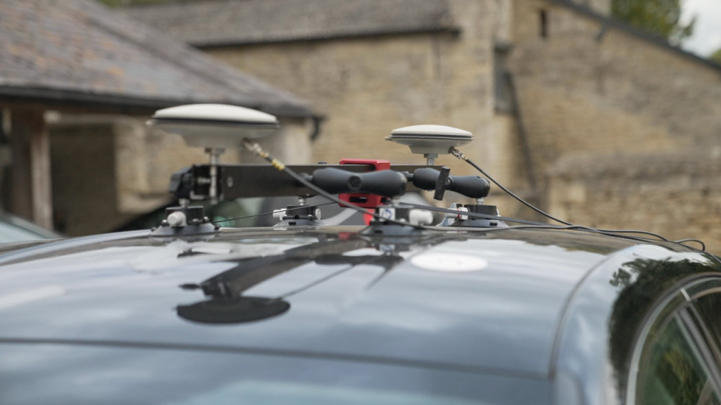
Whatever platform you’re using, you need to ensure that both your surveying sensor and your GNSS/INS are securely mounted to the vehicle. You’re aiming to eliminate any movement relative to the vehicle itself, or the GNSS antennas, which might introduce inaccuracies into your data. The RT-Strut (see image below) from OXTS is one of the easiest ways to securely mount your GNSS/INS in a car.
See our full range of accessories
Depending on your platform, you may also need to consider RF and EM shielding, and vibration dampening, all of which can affect performance. Vibration dampening is something that you will need to manage with any GNSS/INS, but if you are working in an environment where hazards such as dust, water, or electromagnetic interference are common, you may want to consider a GNSS/INS that is specially shielded, such as the RT3000 v4 DO-160.

Summary:
- Ensure surveying sensor and GNSS/INS are securely mounted
- Consider RF and EM shielding if appropriate
- Use vibration dampening to protect accuracy
Step 2: Antenna placement
For land-based mobile mapping, we’d always recommend a dual antenna set up as this will give you a greater heading accuracy and the ability to calculate heading when stationary. For aerial mapping, unless your airframe has enough space, you will only be able to use a single antenna. Using a single antenna may not be quite as accurate as a dual antenna setup, but it’s certainly still accurate enough for many mobile mapping use cases, particularly when you consider a large proportion of aerial mapping projects operate in full GNSS visibility.
When initialising a system with a single antenna, the vehicle needs to move in a straight line so that the system can calculate a heading. Dual antenna setups enable you initialise without moving, which makes the process much smoother.
It’s best practice to mount the antennas as far away from your surveying sensor as is practical, as the antennas can interfere with the sensor if they are too close. As with the GNSS/INS, it’s also vital to ensure the antennas are mounted rigidly to the vehicle frame so that they don’t move relative to the vehicle or to the GNSS/INS. You also need to make sure the antennas are aligned on the horizontal axis – in other words, they are level with each other.
Summary:
- Dual antennas are recommended as long as they can be mounted on your payload
- Mount antennas as far from sensors as practical to reduce interference
- Ensure antennas are level with each other
Step 3: Power and cabling
An OXTS GNSS/INS device comes with a power adapter that plugs into the 12v outlet on a car’s dashboard. For aerial mapping, we generally power the device directly from the UAV or drone’s battery.
Land-based mobile mappers will of course have a multitude of other sensors that require power, such as LiDAR. These will need to be powered independently of the GNSS/INS. In our own test setups, we use a portable power pack to power our LiDAR, but you could of course choose to power it through the car, too.
Cabling is important to consider when working out how to set up an INS for mobile mapping. In aerial mapping payloads the cables need to connect the devices to a power source, each other, and data loggers if you are using them, without affecting the airframe’s ability to function (for instance not causing the rotors to foul in a quad-copter drone). For land-based mappers, the most challenging element is likely connecting the LiDAR and GNSS/INS. This is because the LiDAR has to be mounted on the outside of the vehicle, while the GNSS/INS is often mounted on the inside.
OXTS offers a bespoke roof mount which solves this problem by enabling you to mount your GNSS/INS outside the vehicle with your LiDAR; if you choose not to use this, we generally pass the cables through a window or the boot, and tape them to the roof so that they do not come loose during driving. But ultimately as long as you can secure the cables so they don’t get damaged by the doors, come loose during driving, and don’t put undue stress on the connections, then you should be fine.
Summary:
- Decide whether your GNSS/INS and surveying sensor will be powered via battery or the surveying platform’s own power (such as the 12v outlet on a car)
- Cables need to be long enough to comfortably connect all the components together, but not so long as to affect the platform’s operation. OXTS has a range of cabling options available
- In land-based vehicles, consider mounting the GNSS/INS outside the vehicle to eliminate the need to run cables from the inside to the outside of the vehicle
3) Device configuration
Once the hardware is mounted, the next step in a mobile mapping installation is to configure the device. With OXTS devices this is done using NAVconfig, which is one part of our free suite of post-processing and data visualisation tools, NAVsuite.
Our support documents give you a full breakdown of each configurable part, but in simple terms, NAVconfig takes you through a step-by-step configuration process so you know how to set up an INS for mobile mapping.
- Decide whether to use a previous configuration, start a new one, or modify a previous configuration.
- Define the orientation of your device relative to the vehicle.
- Define the positions of your GNSS antenna(s) relative to the device.
- Configure no-slip constraints to ensure stability when GNSS signal is reduced.
- Define how differential correction data will be provided (RTK, NTRIP, or similar).
- Input the details of your LiDAR if you are using one.
- Configure the outputs from the GNSS/INS, including specifying whether to use NCOM or UCOM (OXTS proprietary data formats), output over Ethernet, serial or CAN, accept CAN inputs, and what triggers will be used.
- Configure time synchronisation details (more on this later).
- Set how the device will initialise (stationary or while moving).
- Define the GNSS environment (open sky, partly obscured, or frequently obscured).
- Define other elements of the environment, such as vibration levels, local coordinates, and so on.
For road-based mobile mapping, we recommend also activating lateral and vertical advanced slip. These constrain the GNSS/INS to the vehicle frame to reduce slip.
Summary:
- Follow the steps in NAVconfig to configure your GNSS/INS. Take care to make sure all the configuration steps are completed accurately.
- You’ll also need to configure your surveying sensors, and synchronise them with your GNSS/INS for accurate data collection
4) Sensor configuration
Just as you have configured your GNSS/INS, when thinking about how to set up an INS for mobile mapping, you will also need to configure your sensors. This is especially important as OXTS devices can use the data from your surveying sensor (particularly LiDAR) to improve its own accuracy in areas where GNSS signal is weaker.
First, follow all the configuration steps in your sensor’s user manual. If you are using a LiDAR sensor, then you should follow two additional steps:
- Enter the LiDAR make and model into NAVconfig. This enables you to store the data on the GNSS/INS if you want to and your survey size allows (larger surveys may collect more data).
- In OXTS Georeferencer, you will need to enter the lever arm for your LiDAR.
OXTS Georeferencer is our specialist software for georeferencing LiDAR data. It is also where you process your INS and LiDAR data for boresight calibration (see below).
Learn more about OXTS Georeferencer
5) Time synchronisation
Ensuring that the clocks in your sensors are synchronised is vital to ensuring the final data is usable. The key here is finding a common synchronisation protocol between your survey sensor and your localisation sensor.
OXTS GNSS/INS devices support a range of synchronisation types, including PTP, gPTP, NMEA, and PPS. Most current LiDAR sensors support PTP, with older models supporting PPS and NMEA. PPS and NMEA can be highly complex to set up, therefore in most cases, PTP or gPTP will be preferred.
The step-by-step instructions for setting up PTP and gPTP synchronisation between your sensors can be found here – feature guide: PTP and gPTP
6) Boresight calibration
For those using LiDAR sensors to survey, such as those from Hesai or Ouster, there is a final step in the mobile mapping setup process called boresight calibration. It precisely aligns the coordinate frames of your GNSS/INS and your LiDAR to ensure that the final georeferenced point cloud is as accurate as possible, eliminating blurriness and double vision (objects appearing twice in the point cloud). The difference between point clouds generated without boresight calibration and with is quite remarkable.
In the before and after comparison below, you can clearly see the lampost appear twice pre-boresight calibration, and only once after.


To perform a boresight calibration, you need to complete a short, two-minute data collection around a calibration ‘target’ before your main survey. There are two types of ‘target’ you can use. We have dedicated boresight calibration targets that are available to buy, or if you are surveying near to walls or similar flat planar surfaces, you can perform the calibration using those.
Once you have collected the data you need to save it and then begin your main data collection project. At the end of the survey, upload your LiDAR file and your navigation file into OXTS Georeferencer and in the boresight calibration feature, click ‘run boresight calibration’. The software will then calculate the angle offsets between your LiDAR and GNSS/INS that you can then input into the OXTS Georeferencer. The result – point cloud data that is free from blurring and double-vision.
Note: Providing your set-up doesn’t change, you can use the same boresight calibration data on your next data collection project.
Summary:
- Boresight calibration precisely aligns your GNSS/INS and LiDAR to maximise accuracy and eliminate double vision in the final point cloud
- It requires a short, two-minute data collection at the start of the survey, either around targets or around a structure with walls
- The process is simple. Upload your boresight survey LiDAR and GNSS/INS files to OXTS Georeferencer and click ‘run boresight calibration’
- The software will then calculate the angle offsets between you LiDAR and INS to a tenth of a degree.
7. Data validation
Before you embark on a full-scale survey, it’s good practice to verify that your setup is correct with a short data-gathering mission. The key is to use NAVdisplay to check your data in real time. NAVdisplay shows you the status of the GNSS/INS, and the data you gather. You can also check that your clock synchronisation is working properly with no unexpected offsets.
This is an important step as it often uncovers issues that you weren’t expecting or couldn’t anticipate. We recommend that you go right through from setup and initialisation to post-processing, so that you have tested every part of your process and know exactly what to expect.
Summary:
- Conduct a short survey before your real mission to ensure everything is set up correctly
- Run the entire process, including post processing, to make sure you catch any errors
8. How to set up an INS for mobile mapping – common pitfalls and how to avoid them
After helping thousands of customers to set up their devices, our customer success teams have noticed some recurring challenges customers have. Here they are – and how to avoid them.
- Time synchronisation issues
Clock synchronisation can be fiddly and technical, but many of the issues we see are a result of making assumptions instead of reading the instructions for your aiding sensor. Always make sure you read the instructions fully so you aren’t assuming anything – and make sure you test methodically.
- Ghosting or blurriness in point clouds
The nemesis of any LiDAR surveyor, blurriness or images appearing twice (also known as double vision) is often caused by inaccuracies between the coordinate frames of the LiDAR and the GNSS/INS. It really highlights the importance of the boresight calibration tool, as it is the only way to be sure that your the coordinate frames are measured accurately – something that is incredibly difficult to do by eye.
- Position drift in urban canyons
Mobile mapping systems shouldn’t be restricted to operate only in open-sky environments. However, in many cases, as soon as GNSS disappears, position drift can quickly get out of hand, rendering data unusable. The true value of a mobile mapping system comes from its ability to collect accurate data, both with and without GNSS. To combat position drift, the OXTS gx/ix algorithm tightly-couples GNSS and IMU data to ensure position drift is kept under control during a survey.
We’re here if you need more support
Our aim when designing our GNSS/INS devices was to make them as simple to set up as possible for a high-precision sensor. But we know that different mobile mapping setups create unique circumstances and challenges that don’t always have an obvious solution. For those situations, our global support team is on hand to help with advice and guidance to ensure your work stays on track.
To ask us a question about setting up your OXTS GNSS/INS for mobile mapping, click below.
Download the RT3000 v4 Datasheet
Learn more about our flagship mobile mapping GNSS/INS the RT3000 v4


