 Chinese
 German
 Spanish
 Japanese
 Korean

Sensor fusion is the science of combining data from multiple sensors to produce a single output.
In this blog, we’re getting into the detail of sensor fusion in mobile mapping, explaining why it’s important and how it works.
Why sensor fusion in mobile mapping matters
Sensor fusion in mobile mapping offers a range of benefits. Ultimately, the goal is to produce position and orientation data that’s as accurate as possible for direct georeferencing. This matters for mobile mapping professionals because it enables them to conduct surveys in a wider range of environments, and potentially offer new types of surveys – depending on the sensors being integrated.
Being able to survey accurately in places that others can’t could also be a crucial differentiator for a mobile mapping business.
Of course, it’s worth mentioning that even a basic GNSS/INS that operates in open-sky environments is fusing GNSS and IMU data, and OXTS has been perfecting this for over 25 years now. But, fusing additional sensor data into the solution is a major priority for forward-thinking mobile mappers, as they try and achieve the following benefits:
Redundancy in different environments
The sensors used for measuring position aren’t infallible. Changes in conditions, or even just random errors, can cause traditional positioning technologies to introduce inaccuracies into a dataset. Sensor fusion helps to mitigate that by providing supporting data from other sensors that behave differently. For example, if you move through a tunnel and your GNSS signal disappears, you can potentially use data from a LiDAR scanner to compensate for the missing GNSS data.
Freedom to move between environments
Increasingly, surveyors and mobile mappers are looking at surveying environments where GNSS signal isn’t available at all – either at the request of clients, or to proactively offer services that differentiate them from the competition. Primary examples of these environments are underground and indoor spaces. This is where sensor fusion in mobile mapping comes into focus.
There are mapping solutions that already exist for these spaces – but they often don’t work well in outdoor conditions. So, if you need to survey a site that has both indoor and outdoor spaces, additional complications can arise.
Taking a sensor fusion approach allows you to combine indoor and outdoor localisation methods into the same solution, so you can transition seamlessly between environments using a single surveying payload.
Contact us to learn more about this.

How IMUs, GNSS and other sensors interact
The core: an IMU
Now we get into the detail. In any sensor fusion system, there is generally a core sensor to which all the others connect. In the vast majority of systems, that’s an inertial measurement unit, or IMU. An IMU contains accelerometers and gyroscopes, which measure changes in angular momentum, velocity and acceleration. This data is passed through an algorithm known as a Kalman filter, which filters out data that is likely to be erroneous, and uses the data from the IMU to calculate estimates about the IMU’s position and movement.
The next layer: GNSS
Where things get clever is when you pass data from additional sensors into the Kalman filter to make the estimates it produces more accurate. The most common sensor data to fuse into an IMU is arguably GNSS data, which provide position and altitude measurements. A system that fuses IMU and GNSS data is generally referred to as inertial navigation systems, or GNSS/INS. Recently, though, progress has been made in fusing other sensors into the solution, to make it even more robust.
As mentioned, this is what OXTS has been working on since our founding, and it’s one of the reasons our devices have a reputation for providing highly reliable and accurate data.
The next generation: LiDAR and other sensors
The most popular sensor at the moment to fuse into a GNSS/INS is LiDAR. Short for Light Detection And Ranging, LiDAR is a powerful sensor that is commonly used for sensor fusion in mobile mapping. It fires laser pulses which bounce off objects around the sensor, and by measuring the time it takes for the pulse to return the LiDAR can accurately measure the distance from the sensor to the point. Some complex work is needed to turn this data into measurements that can be used by a Kalman Filter – but there are integrations out there (including our own) that make it easier.

Other sensors can be integrated too. Wheel speed sensors (also known as wheel tick sensors) have been used by automotive testers for years to improve accuracy; they can also be used for sensor fusion in mobile mapping, as long as the vehicle is land-based and has wheels.
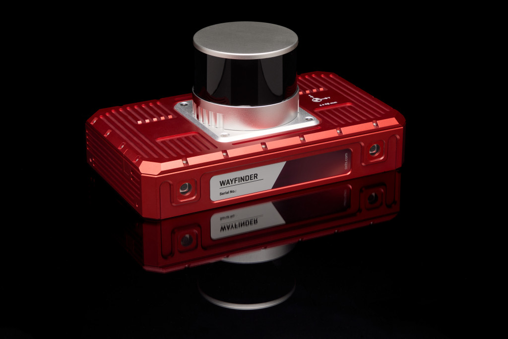
Cameras can be integrated, with may off-the-shelf solutions providing camera-based odometry. And there are many more sensors that could be used. As long as you have the technical expertise to integrate the data correctly, you can integrate a huge range of sensors to improve accuracy. At OXTS, our philosophy is that every sensor has its own strengths, which can be used to compensate for the weaknesses of other sensors in various environments. You can see that philosophy in action in our newest product, WayFinder Prime, which integrates a GNSS/INS, LiDAR, and cameras to provide a turnkey navigation solution that functions in any environment.
But what expertise do you need? Let’s look at some of the key considerations for successful sensor fusion in mobile mapping.
Sensor synchronisation and calibration
These are two foundational considerations of sensor fusion. Let’s look at each in turn.
Synchronising sensors
In multi-sensor navigation setups, it’s vital that your sensor’s internal clocks are all synchronised. If they aren’t, then the whole system can fall apart.
In most modern systems, this is done using PTP, or gPTP. All OXTS devices support PTP and gPTP setups, and can either act as the master clock (so all other sensors align their clocks with the GNSS/INS), or as a client, syncing up with another device’s clock. Again, this can be an important consideration for sensor fusion in mobile mapping.
Sensor calibration
If synchronisation is about getting sensors to agree on when, calibration gets sensors to agree on where. All sensors produce data in what’s known as a reference frame. So for instance, movement could be reported in x,y,z format – we’ve moved 3 cm along the x axis, 5 cm along the y axis, and 2 cm in the z axis. Other sensors might report that same movement in a forward, lateral, down format – so 3 cm forward, 5 cm laterally, and -2 cm down (or 2 cm up!). As a first step, you need to convert all the data from your sensors into a common frame of reference, so that the Kalman Filter can process them correctly.
Once that’s done, you also need to account for the differing positions of your sensors. Each sensor will be in a slightly different place on your payload, which means they will calculate movement slightly differently – especially when turning, since a sensor on the outside of your payload will travel further than a sensor in the middle of your payload.
On top of this, sensors might not even be pointing the same way. A side-mounted LiDAR pointing sideways from the car would report forward movement as lateral movement, for instance. These variations need to be accounted for using lever arms: a set of measurements that describe the difference in position and orientation of your sensor from the core sensor – in this case, the IMU.
You can get down to a further level of accuracy with LiDAR calibration by performing boresight calibration. A boresight calibration aligns the LiDAR and GNSS/INS coordinate frames, accurate to tenths of a degree. For LiDAR surveyors, boresight calibration has dual benefits: it improves the accuracy of LiDAR data for navigation purposes, and also improves the accuracy of the final point cloud survey.
Fusing the data
Once you’ve set up synchronisation and calibrated your sensors, you’re nearly ready to start performing sensor fusion.
The calibrations you’ve performed – aligning coordinate frames and lever arms – will be stored in the interface between your external sensors and your core sensor; that interface will take the outputs from your sensors and convert it into measurements the IMU’s Kalman Filter can work with.
Another important element to include in this interface is what’s known as covariance. This is an estimate of how accurate your data is, which the Kalman Filter uses to decide whether to keep or discard a measurement from that sensor. You can usually find this information in your sensor’s documentation; if not, there are other ways to work it out, such as in our documentation for sensor fusion using our generic aiding data (GAD) Interface.
After you’ve got everything configured, you’ll need to spend time testing everything to make sure you’re getting the results that you need.
Need support?
We hope that this article has helped you understand how sensor fusion in mobile mapping works and progress your own project. If you’re still finding things tricky, our engineers might be able to help you. We’ve been working on sensor fusion for years, so our engineers have seen a lot of the different challenges that can crop up and can help you work through them.
If you want to know more about sensor fusion in mobile mapping payloads, use our contact form to get in touch.
Download the WayFinder Prime Datasheet
Learn more about the specifications you can expect from the WayFinder Prime sensor fusion system.


