 English
 Chinese
 Spanish
 Japanese
 Korean

This article introduces how users of OXTS RT series GNSS/INS can follow the correct configuration, initialisation, and warm-up steps to fully exploit the accuracy of RT series products.
Whether you are conducting vehicle dynamics or ADAS tests at a proving ground (such as an open test track or closed road with good GNSS conditions), or working on surveying and mapping projects (such as road-based mobile mapping, or LiDAR surveying), following the RT-series best practice workflow described here will help ensure you achieve the most reliable data and give you confidence when using our devices.
All explanations in this article will be based on OXTS’ flagship product RT3000 v4. Users of other models can also refer to this guide, and we will note any steps where differences exist.
1) Hardware Installation
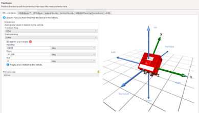
a. IMU orientation
The RT unit (the red box) should normally be installed flat and aligned, with the misalignment angle to the vehicle’s coordinate system kept within 5°. In this case, you only need to specify the direction in the IMU orientation interface, as the subsequent warm-up process can fully correct this error.
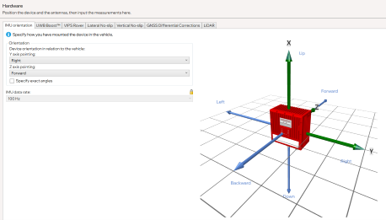
If it is not possible to install it flat, use a smartphone level tool to measure the approximate angle, tick specify exact angles, enter the values, and check that the image on the right matches the actual orientation. The error should also remain within 5°.
b. IMU mounting stability
It is essential that there is no relative movement between the RT unit and the vehicle. To check this, try shaking the unit along the three translational axes and the three rotational axes – in all six directions the device should feel solid, with no play.
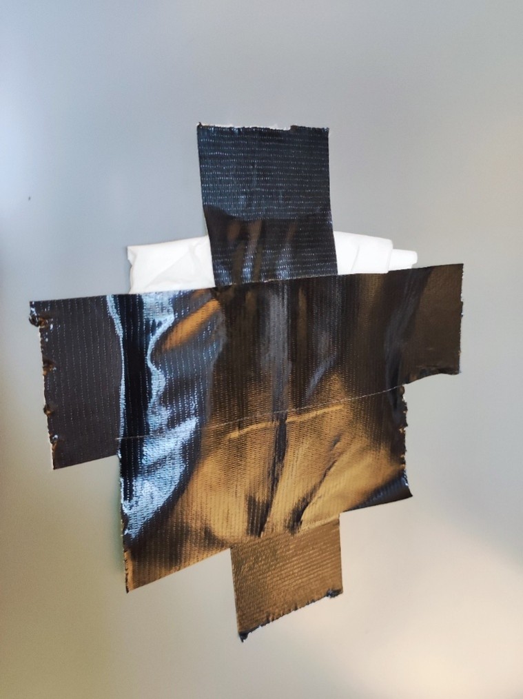
For vehicles without a sunroof, the RT Strut usually secures the unit well. For vehicles with a sunroof, apply suitable cloth tape to the glass surface in advance (and place tissues underneath if necessary) to provide a stable support for the RT Strut’s top contact point.
c. Correct dual antenna configuration
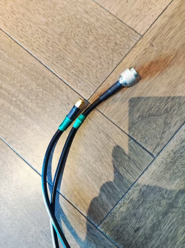
Dual antennas are critical for low-speed heading stability, and we recommend always using dual antenna. Ensure the antennas are not connected to the wrong ports. A useful tip is to mark both ends of each antenna cable with matching colored tape.
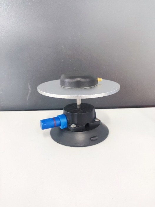
d. Appropriate ground plane solution
For glass-roof vehicles, use suitable antenna ground planes to prevent GNSS multipath effects inside the cabin, as illustrated below:
e. Antenna placement and spacing
Antennas should be mounted at the highest point of the vehicle, with minimal obstruction in between (e.g. no lidar units). The larger the spacing the better – ideally at least 1.5 m apart.
f. Stable power supply
Provide a stable power supply of either 12 V or 24 V. If using the car’s cigarette lighter port, ensure that start-stop (ICE vehicles) or driver-away power cut-off (EVs) features are disabled. If unsure, you can check the device’s FTP logs for RD entries. Multiple RDs in a short period indicate the device has been powered off and on repeatedly, suggesting an unstable power source.
2) Key software settings
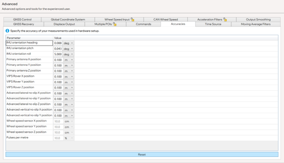
a. Measurement focus and method
Ensure the following accuracy for measurements:
- Dual antenna spacing accuracy: within 0.5 cm
- Lateral slip and longitudinal slip: within 10 cm
- Other distance parameters: within 10 cm
Practical tips:
- Dual antenna spacing: measure directly from antenna connectors using a tape measure.
- RT-to-ground: measure from the RT reference point to the vehicle floor, then add floor-to-ground height.
- Antenna-to-IMU: measure height directly to the roof; for longitudinal and lateral distances, use vehicle projection reference points.
b. Lateral and Longitudinal Slip Configuration
These settings must be completed. They help the RT calculate the vehicle’s true attitude, which is essential for vehicle dynamics tests and when using the device as the hunter in ADAS testing.
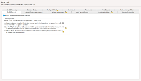
c. GNSS Control
For test track users, select Receiver Mode in the current version.
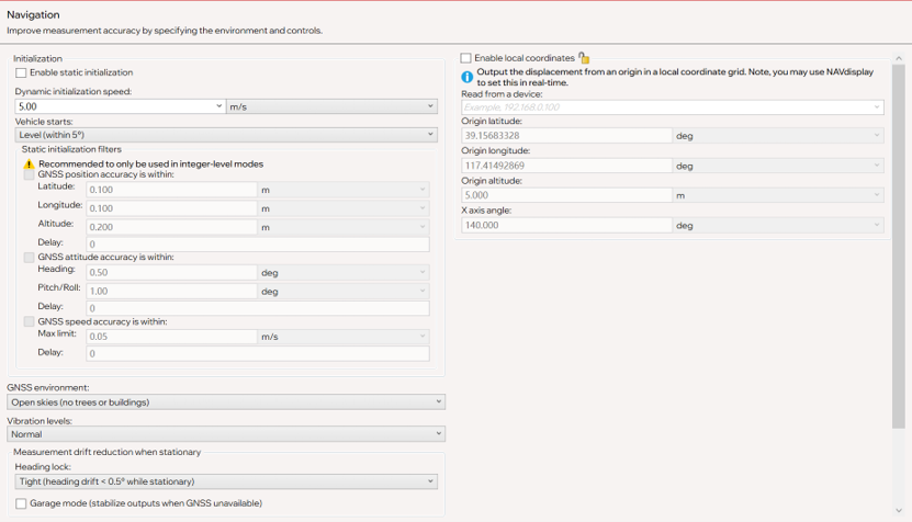
d. Initialisation speed
We recommend setting this to 5 m/s. Note: if you do not want the device to initialise yet, keep the vehicle speed below this threshold.
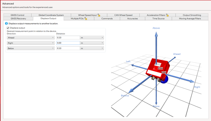
e. Displacement output
Displacement output allows users to calculate target positions, but it increases acceleration noise (which filtering can reduce but not fully eliminate). We recommend keeping 3D distance output below 1.2 m.
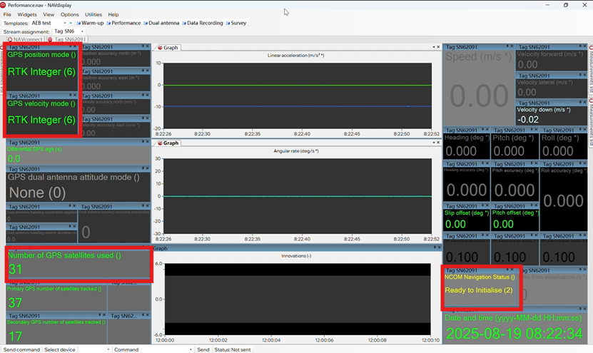
f. Expected NavDisplay Indicators after Setup
- Satellite count: typically 28–34. In receiver mode, RT3000 v4 will track all visible satellites but only use the most optimal ones. If “0” is shown, check the dual antenna template → bottom left corner “on/ok” to confirm antenna connections.
- With differential corrections successfully applied, the top left should show RTK integer.
- Device status (right-hand side) should display ready to initialise.
3) Initialisation and Warm-Up
a. Initialisation
Accelerate in a straight line until exceeding the configured initialization speed (usually > 22 km/h).
b. Warm-Up and Configuration Validation
During warm-up, the device performs three main tasks:
- Calibrates IMU scale factors and biases (internal parameters)
- Aligns the RT coordinate frame with the vehicle coordinate frame
- Calculates the precise position of the IMU relative to the antennas
c. Required Vehicle Dynamics
- Drive and perform the figure of eight
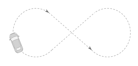
- Constant-speed circles with decreasing radius
- Straight-line acceleration and braking > 30 km/h
- Slalom maneuvers
Thanks to the new IMU10 technology in the RT3000 v4, only 5 minutes of normal driving dynamics are needed (no need for aggressive maneuvers). Optimisation begins immediately after initialization, so once the straight-line acceleration is done, proceed directly with the driving maneuvers.
For older models (RT3000 v3, RT3003, RT3002), warm-up requires 15 minutes and more aggressive driving.
d. How to Verify Configuration
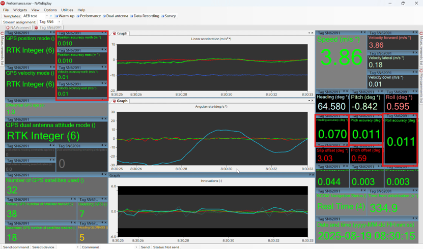
Check the Performance → Innovation curve:
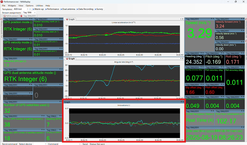
- If it fluctuates strongly at the start, some configurations may be incorrect (e.g. orientation misconfigured, measurement errors, or swapped antennas).
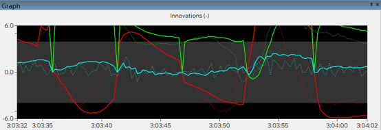
- If fluctuations appear under certain dynamics but remain within the gray band, repeat those maneuvers to reduce ambiguity.
- If the curve converges near zero under all dynamics, the warm-up is successful. Also check the red-boxed parameters on the Performance screen for confirmation.
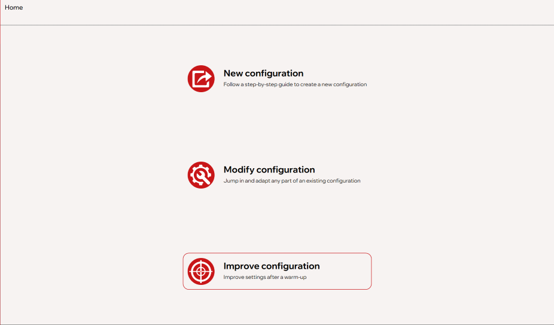
4) Optimising the Configuration
The goal of optimisation is to write the improved parameters into the device configuration file. The process is as simple as clicking Weiter.
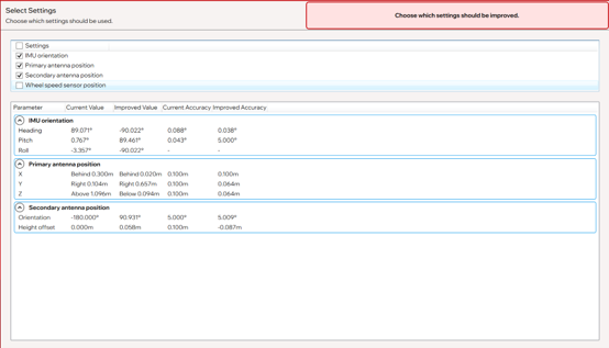
⚠️ For automotive testing: If no wheel speed sensor is connected, do not tick the wheel speed option. Once optimisation is complete, the device will reboot.
A note on orientation adjustments
You may find that optimization significantly changes heading, pitch, and/or yaw. This is normal, since multiple combinations of heading/pitch/yaw can correspond to the same physical orientation. For more detail, search the term “gimbal lock.”
5) Post-Warm-Up Testing
After device startup, repeat initialisation and warm-up. Normal signs include:
- Innovation curve remains stable
- After ~5 minutes of dynamics:
- Slip offset < 0.10
- Pitch offset < 0.05
- Accuracy indicators all within expected values
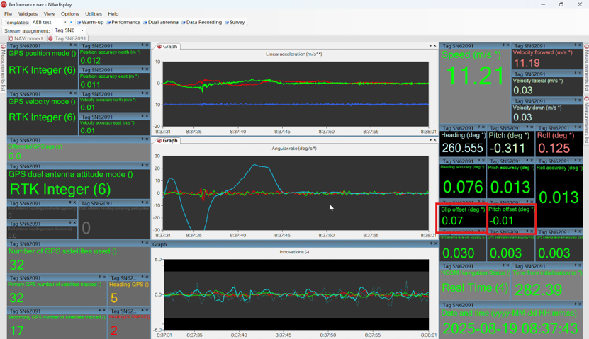
At this point, the device will measure all data at its highest possible accuracy.
Two common questions
- What if the device has been moved significantly?
→ We recommend starting configuration from scratch. - What if the device has only been moved slightly?
→ Go to Advanced → Accuracy, reset accuracy, and repeat the steps in this guide.
6) RT-Series Best Practice – Final Notes
This guide covers the complete preparation workflow of the RT series devices, including configuration, initialisation, and warm-up. These steps are sometimes overlooked, but they often determine the final data accuracy.
For automotive testing users, these operations ensure precise vehicle dynamics and ADAS test results. For surveying and mapping users, they guarantee high-quality GNSS/INS trajectories and reliable point cloud data.
Throughout this article, we have tried to make clear what you should expect to see at each step, so that you can easily confirm whether the process is correct – for example:
- “This step looks right” or
- “This indicates a possible mistake in an earlier step”
Once familiar, these steps take very little time but bring huge benefits: whether in testing or mapping, you will obtain reliable, controlled, and highest-accuracy results.
We strongly recommend that all RT users take the time to follow and practice these key steps. If you have any questions or encounter situations not covered here, please do not hesitate to contact us.
Jeremy Li
Senior Customer Support Engineer, OXTS
RT3000 v4-Datenblatt herunterladen
Learn more about our flagship GNSS/INS the RT3000 v4


